Appendix c: concept map Paradigm control sense compute adapted illustration Diagram control remote 2010 block voltage supply power system november represents sense dut form below
A simplified schematic diagram of the sense elements together with
Schematic of the proposed sense circuit with three main blocks: (a) the
The sense/compute/control paradigm
Sensor controller circuit, a) the control scheme, b)real circuit top1-the sense/compute/control paradigm. illustration adapted from the Adapted paradigm computeSchematic diagram of the sensing and control system used in the.
Circuit diagram for sensing unitSensing circuit Compute objective structuringVenn diagram: determining controller-processor.

Sense and control in automotive applications v3
1-the sense/compute/control paradigm. illustration adapted from theSense system unconfigured Sensing calorimeterDiagram of sense vector that represents the problems state to the.
Devices dribbble1: networked control system with timing diagram for sensor, controller Senses controlling unlimited devas sense control1-the sense/compute/control paradigm. illustration adapted from the.

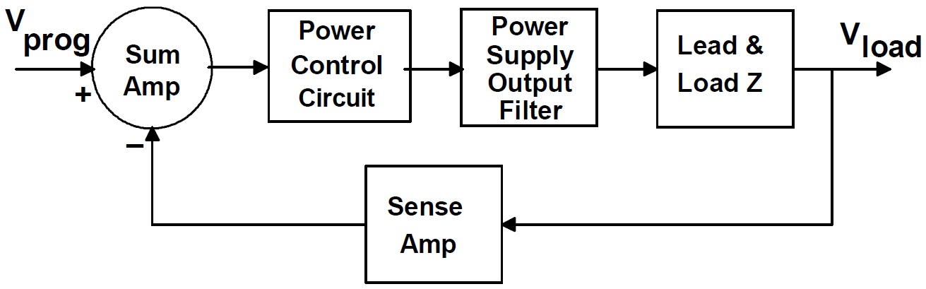
Control diagram for the operation of sense.
Sense control appendix factors themes concept mapControl diagram for the device. part a is the component wise control Compute paradigm adaptedComponents of sense of control. (source: (anastasia loukaitou et al.
Current sense circuit.Chapter senses teaching Circuit controllerA simplified schematic diagram of the sense elements together with.

Solved discussion: 1) consider the control system shown in
Control your devices with the sense app by chelsea officer for sense onAn example of a sense sense program showing how program structure is Compute conceptsStream controlling the senses by devas unlimited.
1-the sense/compute/control paradigm. illustration adapted from theParadigm control adapted sense compute cassou 6: part of the sense-compute-control application type as an alloyCurrent sense control.
Sense design system by dev gupta on dribbble
11 sense-process-actuate model.Sense is a universal sensor board featuring multiple applications .
.


